Users can remove all display ads (not sponsors) for a small fee. Click for info (must be logged in)

Discuss Is my UFH piped in correctly? (With photo) in the Plumbing Jobs | The Job-board area at PlumbersForums.net

Status
Not open for further replies.
S

StevenW

Hi Guys,

Quick question for you,

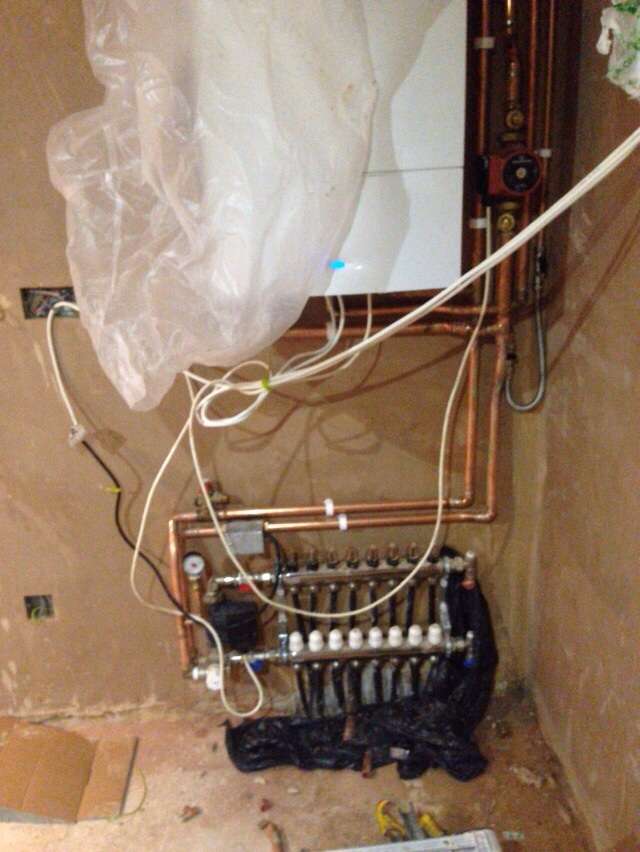
I have just had my underfloor heating piped into the main circuit by a plumber. I have not used him before.

My setup is a Sealed system, Convetional boiler, S plan plus with 3 zones. 2 heating/ 1 DHW.
The UFH uses a an RWC combined thermomix valve/pump assembly.


The flow that supply's the UFH setup has been Tee'd off before the main central heating circuit pump.
Is this correct? It was not like this previously and all schematic diagrams I have looked at show the flow branching off to the UFH zone AFTER the pump, as like the other 2 zones.

Last night, we had the UFH heating on and the other 2 zones off. The boiler seemed noisy and the system pressure was up over 2 bar.

As I can see it, when only the UFH zone is on, and no demand from the other 2 zones, the Auto bypass valve is going to be constantly forced into bypass by the main pump.
Also, as the flow to the UFH is branched off on the intake side of the main pump, the pressure differential between the flow and return of the UFH is likely to be higher on the return side.

I am an aircraft engineer by trade, not a central heating engineer. So any advice and information would be greatly appreciated.

Many thanks in advance!

Steve.


p.s. Ignore the temporary wiring in the photo please!


QSPl6E.jpg
 
On a conventional system it should be boiler,pump,auto bypass, then zone valves. It looks like your manifold does not incorporate a pump. A seperate pump has been fitted. The zone valve for the u/f is normally before the u/f pump.
 
Hi Kodak,

Sorry for poor photo quality.

That black blob to the left of the manifold is the circulation pump for the UFH. See the cable going to it.

It uses the combined Reliance Thermomix valve/pump assembly. Quiet common I believe.

There is a zone valve also before this UFH pump. There is o problems with this part of the set up.
It's just the take off for it from the main heating loop, looks to be the wrong side of the pump.
And from what you have said in the first part of your reply, it is wrongly done.
 
Last edited by a moderator:
The tee for the u/f circuit flow should be after the grundfos pump. Sorry I couldnt see the manifold pump properly.
 
Hi
Not sure on pipe connections on a Worcester. But is that pump on the return?
 
Flow on the left, Gas supply in the middle, Return on the Right hand side.

That T is on the flow outlet from the boiler but before the main pump. Which I think is incorrect?
 
Flow on the left, Gas supply in the middle, Return on the Right hand side.

That T is on the flow outlet from the boiler but before the main pump. Which I think is incorrect?
You are correct. It basically has two returns! Will need altering.
 
O dear.. Had UFH put in at a job we put boiler + cylinder. God the guy was absolutely clueless. Wired pump into permament live, manifold was screwed in well p*ssed on the wall. Looks like underfloor heating sector doesnt attract the brightest of minds..
 
Yes you are correct your system has been piped up incorrectly.your pump from the boiler should be pumping to the zone valve on the ufh heating as well,the pump on the underfloor heating only circulates blended water around the ufh loops.you still need to pump water to the ufh blending valve.
 
Should be an easy fix at least, but the Ufh won't be very effective as it is.

Is that an additional relief valve fitted above the Ufh zone valve??
 
It's not an additional relief valve..
It's the only relief valve on the main CH circuit. Is it correct?
 
It's not an additional relief valve..
It's the only relief valve on the main CH circuit. Is it correct?

Should be okay, normally the expansion vessel, fill valve, pressure gauge & relief valve is all together... Yours looks to be spread about lol!
 
I must admit, it was my request to position the expansion vessel upstairs due to us having units running along the utility wall and wanting the space available.

Bit disappointed in the condensate pipe drain, no step up adaptor, just dangling in a straight pipe, and the amount of brick missing after he's drilled the wall for the Px relief valve vent:

490jHS.jpg
 
It's better without the reducer on a soak away as it acts as an air break.

If the soakaway blocks the water won't flood the boiler, which is more common than you think!
 
Me personally idve piped it totally different,, how big is your property ??? , where is the expansion vessel ? i do hope its piped correctly as it does matter where its teed into to cope with expansion properly, your system pressure will rise to near 2bar due to expansion, ,
You couldve had a tiny LLH depending on system size and pump output and the pipework totally changed below the boiler to ,make more efficient,
 
Nostrum, I will maybe get a 36mm elbow to go over it, to appear aesthetically pleasing but still give an air break an leave the reducer out.
As it is, he didn't even debut the rough bit on the pipe. I struggle to find tradesmen who take pride in their work.
 
My property is a 340sqm detached house in rural East Anglia. 1950's built.

Thanks for your comment Kris.

Those are fairly open ended statements... Please expand on what you've started to say? Would be very interested and greatful to hear your thoughts and some professional advice.
Needless to say the layout of the pipework below the boiler is not my design.

However the location of the boiler is a slight compromise, I agree, due to the underground LPG tank positioning on our plot. And the loft area being used for living space/vaulted gable end/large window setup so unable to position there.

The layout runs 28mm feed and returns up to a central area upstairs in the property. Where the zone valves are located, where it then distributes off to the upstairs Radiators and water cylinder.
The exspansion vessel is located in the same area as these zone valves.

Any help and advice, is greatly appreciated.
 
Last edited by a moderator:
Status
Not open for further replies.

Reply to Is my UFH piped in correctly? (With photo) in the Plumbing Jobs | The Job-board area at PlumbersForums.net

Similar plumbing topics

Hi, Later this year I am going away for a 2 week holiday and as the weather will be warm there is no need for the heating to be on and arguably...
Replies
1
Views
167
P
  • Question
Boiler is SIRIUS THREE FS 70 Potterton commercial. Situation: We are small building contractors and my labourers managed to damage the radiator...
Replies
2
Views
133
  • Question
Ideal Logic 24, Previous problem was that the hot water was only cold or barely warm if the heating was in use. If heating was off and boiler cold...
Replies
2
Views
210
S
Hi, I seemed to have a blockage in kitchen sink. A plumber came and cleared all the pipework that is visible inside my home (there was debris and...
Replies
2
Views
153
Sonya K
S
We run a community village hall and have a large kitchen provided for the use of hirers. This includes a Lincat SLR9 gas cooker which I believe is...
Replies
5
Views
543
Back
Top
AdBlock Detected

We get it, advertisements are annoying!

Sure, ad-blocking software does a great job at blocking ads, but it also blocks useful features of our website. For the best site experience please disable your AdBlocker.

I've Disabled AdBlock