Search the forum,

Discuss Flow gauges for central heating pipe work in the Plumbing Jobs | The Job-board area at PlumbersForums.net

It was a grundfos 25-80, beast of a pump, think it was 20 litres a min on his laptop but the pump just had the usual 3 settings, it didn’t display watts.

Also I suppose it’s not really the performance of the pump I’m interested in. I’m interested in the performance of the system.

So how much force is the pump generating and how much is lost going round the various pipe runs.

I realise we could work this out on paper if we knew every bend and pipe run but in reality it’s either impossible or just too much grief!

So back to the original premise. Is there a way of measuring the frictional resistance of a heating system using gauges / flow meters / electronic sensors?
 
Very informative. The bit about constant pressure and underfloor heating confirms what I had read in some Grundfos literature - not that I can find it now. I guess that would also apply to microbore systems where the rads are fed, individually, from a manifold.

The other bit which struck me was the statement that current high efficiency pumps "are seriously lacking in sensory input. They can detect the system resistance and, if they have a built-in temperature sensor, they can detect system temperature." This means that all the "data" which is presented by the Grundfos Alpha 3 App is derived (from frequency, current etc?), not measured directly. I have read criticisms of the Alpha 3 that the data is not always accurate.
 
Yes, all these pumps derive the head and flow from the power (easily measured), the frequency (again easily measured) BUT they must also know the pump&motor efficiency at every point on every curve setting, which is literally hundreds of "numbers" as a lot of these pump's PP and CP settings can be increased from say 0.5M to 6M in 0.1M increments, I would love to know how this is done (efficiency calculations). I used my (oil) boiler rated output and the measured deltaT to calculate the flow rate and it compared within 10% of the derived flow from the Wilo power so I suppose fair enough for most purposes.
 
It was a grundfos 25-80, beast of a pump, think it was 20 litres a min on his laptop but the pump just had the usual 3 settings, it didn’t display watts.

Also I suppose it’s not really the performance of the pump I’m interested in. I’m interested in the performance of the system.

So how much force is the pump generating and how much is lost going round the various pipe runs.

I realise we could work this out on paper if we knew every bend and pipe run but in reality it’s either impossible or just too much grief!

So back to the original premise. Is there a way of measuring the frictional resistance of a heating system using gauges / flow meters / electronic sensors?
I'm afraid I can,t give a really meaningful answer to the above, apart from saying that it is physically possible to fit differential pressure and flow gauges to every loop in the system.
 
It’s just overkill though chaps. You are going to get joe public looking at this and thinking it’s rocket science to change a pump when it’s just not. Talk about baffling with science
 
The joe publics that change their own pumps will quickly learn that these pumps have the three traditional "fixed speed" settings, some, who are interested, will play around with the other settings. I suppose the vast majority of pumps are replaced by plumbers who will certainly be aware of these traditional settings and as time is money won't waste too much of their time playing around with the other settings.
 
Last edited:
I think the Alpha 3 displays both the pump head and the flow rate which can be very handy.
It's hard to see how you could measure flow at all accurately within the pump, unless Grundfos have come up with something clever. Easy enough to measure the pressure rise across the pump and use that to predict flow based on the pump curve, but that only works while the pump is performing as new.
For several years I had a minor system noise problem, but didn't suspect the pump. Then the pump itself started vibrating noisily, so I changed it, and the system noise went away. The old pump was badly clogged inside and behind the impeller, so performance down. A genuine flow reading would have indicated a problem, but one based on reduced measured DP and (new) pump curve would indicate high flow. A reading of DP would be useful, as along with estimated system curve would give an idea of actual pump performance.
 
Imagine you had a pressure / flow gauge on your outside tap as soon as it comes out the wall. Then imagine you have one on the end of the hose pipe after its run 20m down the garden. Surely the gauges would read different values?
The pressure at the end of the hose would be lower (if there is some flow) due to pipe friction, but the flowrate is the same for both (conservation of mass and incompressible fluid).
 
It was a grundfos 25-80, beast of a pump, think it was 20 litres a min on his laptop but the pump just had the usual 3 settings, it didn’t display watts.

Also I suppose it’s not really the performance of the pump I’m interested in. I’m interested in the performance of the system.

So how much force is the pump generating and how much is lost going round the various pipe runs.

I realise we could work this out on paper if we knew every bend and pipe run but in reality it’s either impossible or just too much grief!

So back to the original premise. Is there a way of measuring the frictional resistance of a heating system using gauges / flow meters / electronic sensors?

Bit of info here, page 36, not quite what you are after, but interesting all the same.
https://www.caleffi.com/sites/default/files/coll_attach_file/idronics_16_na_0.pdf
 
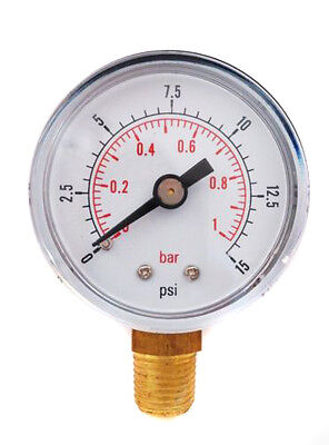
An update on this; I recently installed an S plan at home. I fitted a 0-2 bar pressure gauge straight after the pump and another on the return near the boiler.

You can indeed see the pressure difference on the gauges when the central heating is running.

As the gauges are in the loft and the filling loop gauge downstairs;

I'm getting 29psi with the pump on setting 3 and 20 psi on the return, you can see the pump performance change as I change the speed setting and also the 9 psi loss across the heating circuit.

Interesting!

So if your on a job where you want to see the performance of the pump or the loss across the heating circuit, I'd recommend 0-2 bar gauges.

This also leads me on to the stupid 0-4 or 0-6 gauges that plumb centre sell. If normal operating pressure is 1-2 bar wth is with 6 bar gauges!! :p

Ps I got mine off ebay ;)

 
Have you allowed for the static height (if any) difference between two gauges as 9 psi or 6.2M seems to be a very high system loss??
 
Its not "extra water" or "less water" but loss of pressure or flow.

For example

Imagine you had a pressure / flow gauge on your outside tap as soon as it comes out the wall. Then imagine you have one on the end of the hose pipe after its run 20m down the garden. Surely the gauges would read different values?

Only if the hose is inflating like a balloon or you remove the hose.

Thought experiment: you have a tap with incorporated flow gauge running at 15l/m and then you add a hose. Flow drops to 10l/m. A gauge at the end of the hose must read the same.

Otherwise you have 15l/m going into the hose and only 10l/m leaving the hose, leaving 5 litres of water every minute that enters the hose but does not leave it. So where is that 5 litres of 'extra' water going? If it is going in one end, it must go out the other end.
 
your measuring mas
Only if the hose is inflating like a balloon or you remove the hose.

Thought experiment: you have a tap with incorporated flow gauge running at 15l/m and then you add a hose. Flow drops to 10l/m. A gauge at the end of the hose must read the same.

Otherwise you have 15l/m going into the hose and only 10l/m leaving the hose, leaving 5 litres of water every minute that enters the hose but does not leave it. So where is that 5 litres of 'extra' water going? If it is going in one end, it must go out the other end.
[/QU
Only if the hose is inflating like a balloon or you remove the hose.

Thought experiment: you have a tap with incorporated flow gauge running at 15l/m and then you add a hose. Flow drops to 10l/m. A gauge at the end of the hose must read the same.

Otherwise you have 15l/m going into the hose and only 10l/m leaving the hose, leaving 5 litres of water every minute that enters the hose but does not leave it. So where is that 5 litres of 'extra' water going? If it is going in one end, it must go out the other end.

In litres per min we’re measuring mass over time, the 5 litres hasn’t disappeared. The water is moving slower due to increased frictional resistance.... I suppose it’s still in the pipe?

How about if a hose pipe is 50m long? Would you still get the same performance as if it was 1m long? No, the pressure and flow rate would drop the greater the length, or frictional resistance of the pipe. A gauge immediately out of the tap would give different readings than one on the end of the run.

For example. Yorkshire water have a pumping station, the pump is new and the pipes are new, the gauge near the pump reads 3 bar and a flow cup gives 20 litres a min. Joe blogs has a house 20 miles away. His mains water pipes are ancient and all furred up, he’s getting 8 litres per min from his kitchen tap due to the restriction in the pipes..... the water is there it’s just moving slower

The two gauges on my pipe work are close to the boiler, literally on the flow and return, on a heat only sealed system. The flow gauge is 420mm higher than the return gauge and is located on the positive side of the pump. I turned the pump down to setting 2 as it was a little noisy. I’m getting around a 5-6psi difference across all the pipe work, rads and unvented cylinder. It’s a 2 bed semi, boiler in the loft.

rads are

1000x600 k1 x2
600x600 k1 x2
1600x600 p+
1800x500 k2
 
In litres per min we’re measuring mass over time, the 5 litres hasn’t disappeared. The water is moving slower due to increased frictional resistance.. I suppose it’s still in the pipe?
Okay, so after 2 minutes, we have an extra 10 litres in the pipe; after 10 minutes, another 100 litres in the pipe? In my thought experiment I can't see it happening.
If you've actually carried out the experiment in real life with two flow gauges and I'm wrong, then please let me know.
 
Back to the original premise!

Lets say you’ve just installed a new boiler. Is the pump working? Is it circulating around the byepass or the whole heating circuit? With a gauge on the flow and return you can see the real time pressure loss across the circuit.If it is pumping around the byepass or just the coil then the difference between the gauges will be next to nil. If it’s pumping around the entire circuit you will see a larger difference
 
I fitted a 0-2 bar pressure gauge straight after the pump and another on the return near the boiler.

Have you allowed for the static height (if any) difference between two gauges as 9 psi or 6.2M seems to be a very high system loss??
It's not clear where the second gauge is located. It sounds as if it is on the return as it enters the boiler, in which case the head loss in the boiler's heat exchanger would not be included in the 9 psi.

Edit:

It would help if we knew which boiler you had,
 
Last edited:

Reply to Flow gauges for central heating pipe work in the Plumbing Jobs | The Job-board area at PlumbersForums.net

Creating content since 2001. Untold Media.

Newest Plumbing Threads

Back
Top
AdBlock Detected

We get it, advertisements are annoying!

Sure, ad-blocking software does a great job at blocking ads, but it also blocks useful features of our website. For the best site experience please disable your AdBlocker.

I've Disabled AdBlock