I'm a software engineer diving head-first into the world of embedded systems design and development. This question is basically about "plumbing" -- what's the best way to physically wire up a particular circuit. So:
I have a small microcontroller evaluation module, the CC11EMK, with a 2x5 header debug port.
I also have an evaluation board (the CC1110-CC1111DK: CC1110-CC1111DK - Texas Instruments - RF Evaluation and Development Kits, Boards - Kynix Semiconductor) to program the evaluation module, also with a 2x5 header. (The dongle is in the lower left) below:
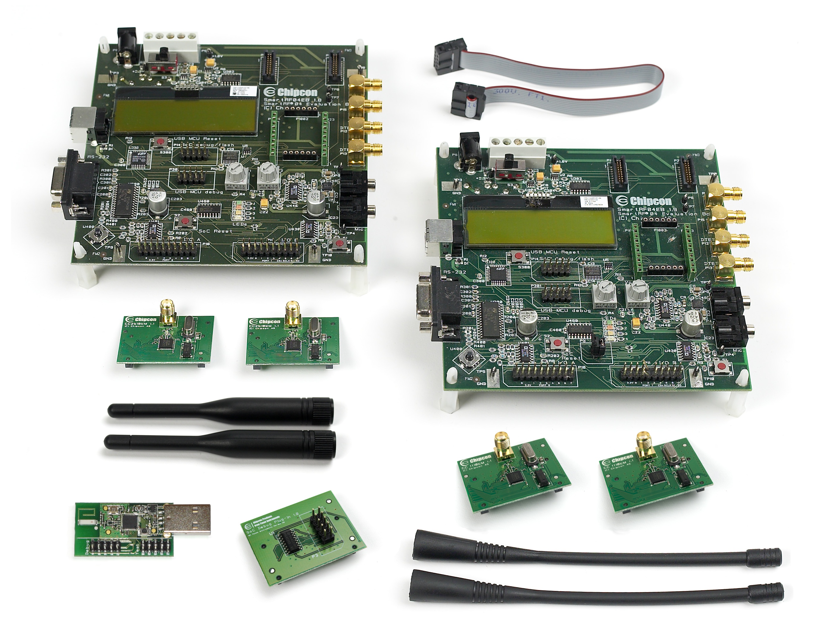
The two are connected with a 10-wire ribbon cable.
My problem is that the microcontroller reset pin is sensitive to noise, causing random resets. Not fun. The datasheet for the CC111 has this to say in section 6.11.1:
The RESET_N pin is sensitive to noise and can cause unintended reset of the chip. For a long reset line add an external RC filter with values 1 nF and 2.7 kOhm close to the RESET_N pin.
I also have some sensors and an SPI bus setup on a breadboard.
What's a relatively simple way to insert the resister and the capacitor into the circuit? I thought I might be able to stick a pair of 2x5 headers onto the breadboard, use two ribbon cables, and wire corresponding pins together with the exception of the reset line, which I'd pass through the RC filter. But I don't think that can work on a breadboard -- the header won't fit over the gutter, so no matter how I do it, I'd be shorting together pairs of pins.
Any suggestions?
I have a small microcontroller evaluation module, the CC11EMK, with a 2x5 header debug port.
I also have an evaluation board (the CC1110-CC1111DK: CC1110-CC1111DK - Texas Instruments - RF Evaluation and Development Kits, Boards - Kynix Semiconductor) to program the evaluation module, also with a 2x5 header. (The dongle is in the lower left) below:
The two are connected with a 10-wire ribbon cable.
My problem is that the microcontroller reset pin is sensitive to noise, causing random resets. Not fun. The datasheet for the CC111 has this to say in section 6.11.1:
The RESET_N pin is sensitive to noise and can cause unintended reset of the chip. For a long reset line add an external RC filter with values 1 nF and 2.7 kOhm close to the RESET_N pin.
I also have some sensors and an SPI bus setup on a breadboard.
What's a relatively simple way to insert the resister and the capacitor into the circuit? I thought I might be able to stick a pair of 2x5 headers onto the breadboard, use two ribbon cables, and wire corresponding pins together with the exception of the reset line, which I'd pass through the RC filter. But I don't think that can work on a breadboard -- the header won't fit over the gutter, so no matter how I do it, I'd be shorting together pairs of pins.
Any suggestions?
