Search the forum,

Discuss Help me understand this pump curve in the Central Heating Forum area at PlumbersForums.net

Messages
5
This pump curve is from a combi boiler with an internal automatic bypass valve.
curve.png

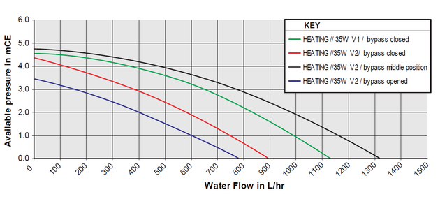
Why is the maximum flow obtained with the bypass valve in the middle position? Shouldn't a fully closed bypass valve result in a higher flow through the main circuit?

Also, any idea what 'V1' and 'V2' mean (no clues in the boiler manual)?
 
V1 and v2 boilers ??

Also the bypass won’t operate until the pressure is overcome so probably had a higher pressure spring than the pump force on an open circuit
 
Could V1 and V2 have any special meaning besides versions of this particular model?

I follow your sentence about the bypass operation, assuming it is some type of spring loaded valve. But this does not explain the curves. The blue, red and black curves must have been generated with the valve held into a particular position and in this situation I would expect the red and black to be swapped.
 
All modern pumps are variable speed with different modes/settings, you could have 3 CC settings, 3 PP settings and 3 CP settings, each of these will have a different closed valve (dead headed) head so perhaps something like that.
 
Had a scan through that but really none the wiser, it states that the bypass is automatic and non adjustable which probably means just a spring loaded bypss so the pump speed is controlled automatically to give a certain by pass based on operating conditions like flow/return dT etc. The pump curve only gives one V1 curve (bypass closed), also don' know what 35W means on all curves, 35W would be a typical A rated pump power.
Other info is that the 24kw boiler max outputs are 17.6kw/24kw, heating/DHW and the 28kw boiler max outputs are 23.4kw/28kw, heating/DHW but with probably the same circ pump.
 
All modern pumps are variable speed with different modes/settings, you could have 3 CC settings, 3 PP settings and 3 CP settings, each of these will have a different closed valve (dead headed) head so perhaps something like that.
If the pump is integrated into the boiler, this may not be possible to adjust. Perhaps the boiler manufacturer saw fit to have the pump made so as to only operate in one mode?
 
The blue, red and black curves must have been generated with the valve held into a particular position and in this situation I would expect the red and black to be swapped.
Proportional pressure pump set to increase head with flow might, hypothetically, send more flow around system with the bypass open, though seems unlikely.
 
You can set up a pump in PP mode with a fixed springloaded ABV to pass a certain flow but as system demand increases so too does the pump head in PP mode which forces the ABV to recirculate more, the opposite to what you require, thats why PP mode is not recommended for external ABVs, constant curve (fixed speed) mode was traditionally the proper mode but all modern pumps now control a good portion of their flowrate in a constant pressure fashion even when running in PP mode, the UPS3 is one of the best (or worst) examples of this.
Its likely IMO that the above pump control is done in PWM mode where invinitely adjustable speed is used depending on the flow and boiler temperature conditions, especially the flow/return temperatures dT.

1680599295652.png
 
I would expect the red and black to be swapped.
I agree, the graph key has been muddled up. I think you have a simple pump with two speeds (V1=black, V2=green) and a simple bypass valve that can be closed, part-open (red), or fully open (blue). There'd be no point using V1 with the bypass open as it would essentially give the same performance as the green and red curves but use more electrical power in the process. I suspect that the V1 setting will use more power, say 45W rather than 35W.

These are the sort of errors that get introduced when technical graphs from engineers are 'redrawn for publication' by non-engineers.
 

Reply to Help me understand this pump curve in the Central Heating Forum area at PlumbersForums.net

Similar plumbing topics

I have a heating system comprised of skirting radiators that form part of a loop from the boiler, round the house and back. Some rooms get warmer than others despite closing off the skirting radiator heat vent. They are designed to house the finned heating pipe and a return pipe, the latter...
Replies
0
Views
80
    • Like
Hello, my Mothers heating failed in the recent UK cold snap. I found the pump was stuck. I have a question about pump orientation. The existing pump flows downwards. The manual for the proposed replacement recommends that it should pump upwards. This would involve rearranging the flow &...
Replies
8
Views
606
Hi All, Looking for a bit of advice on the best way to pipe this. - 24kW Worcester regular boiler in kitchen, approx. 9 years old - unvented tank, zone vavles, pump, expansion is on first floor in airing cupboard - Currently piped as S-plan. - Hive controls. - Would like to fit 6-zone...
Replies
16
Views
970
    • Like
Hi everyone, Just wanted to share my experience with "upgrading" an S plan setup to Opentherm and Vaillant Control Center (VR66). There are a few threads on a few different forums but I wanted to share a full write-up with all the steps needed, benefits and costs. Overall, I fully recommend...
Replies
1
Views
1K
Hello all, I have a WorcesterBosch Greenstar 42CDi classic combi, which is providing DHW fine, but not heating. Was working fine in spring, probably not been used until recently now it's colder. When heating is called for, the boiler fires up ok but soon shuts down the heater as the...
Replies
11
Views
958
Creating content since 2001. Untold Media.

Newest Plumbing Threads

Back
Top
AdBlock Detected

We get it, advertisements are annoying!

Sure, ad-blocking software does a great job at blocking ads, but it also blocks useful features of our website. For the best site experience please disable your AdBlocker.

I've Disabled AdBlock